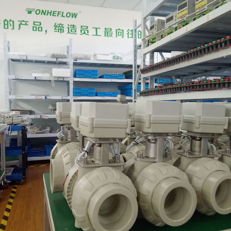
Tonheflow motorized valve manufacturer
Tonhe mainly produces motorized shut off ball valve from 1/4" to 2",
Some valves approved NSF61-G, CE, ROHS and other international certification.
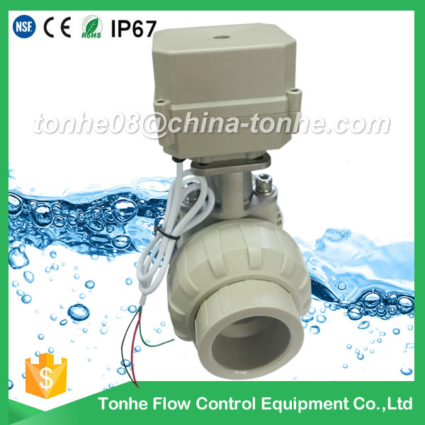
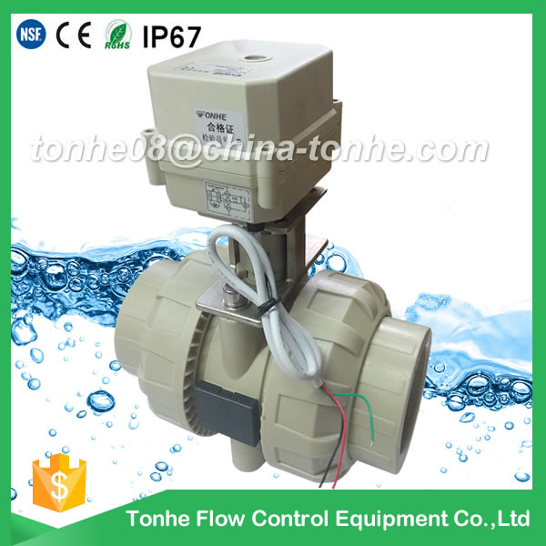
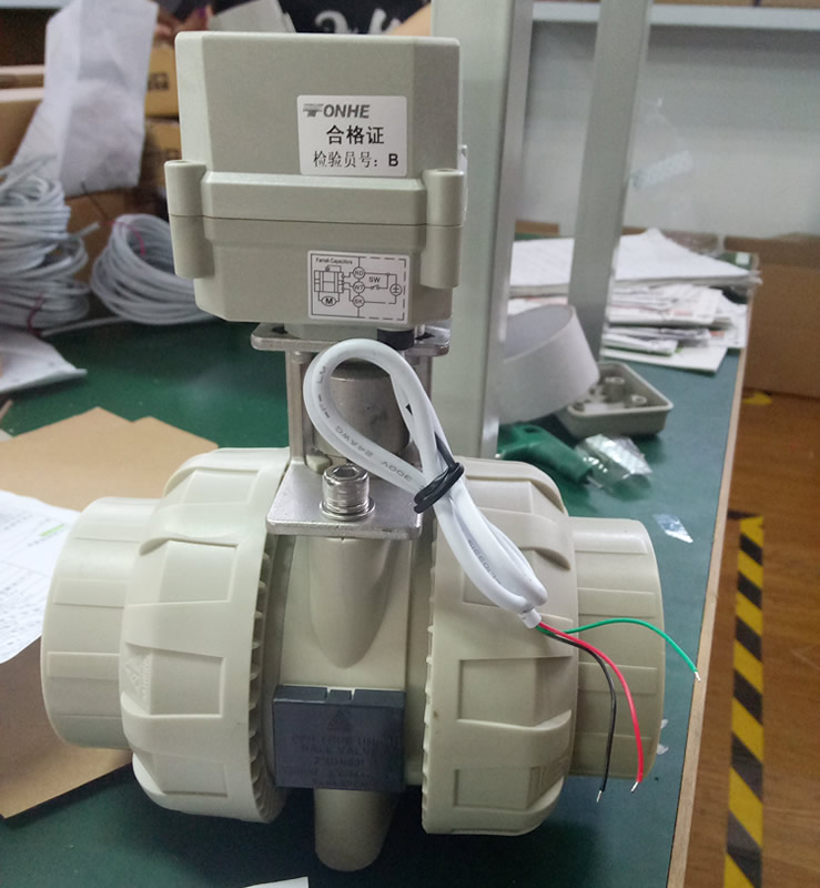
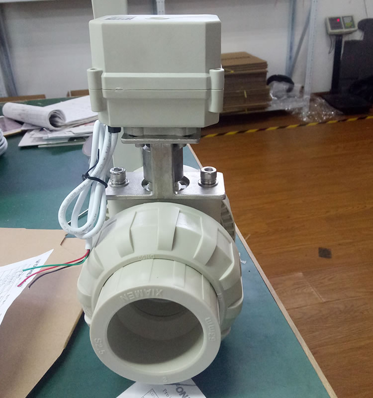
A100-T50-P2-C PP PVC plastic motorized valve DN50 no thread Solvent socket type
Min.Order Quantity: 1 Piece/Pieces
Supply Ability: 5000 Piece/Pieces per Month
Port: ningbo,Shanghai
Payment : T/T, Paypal

Service On Line
Supply Ability: 5000 Piece/Pieces per Month
Port: ningbo,Shanghai
Payment : T/T, Paypal
Service On Line
Tonhe is a china manufacturer, we focus on PP PVC motorized valve(1/2" - 2 1/2"), which are CE, RoHS, IP67 approved, and PVC valve body is NSF61 approved. Our company also SGS ISO9001 approved.
Please see below picture confirm thread below
1)Thread BSP? NPT ? or no thread(Solvent socket type)?2)if you need no thread(Solvent socket type),ANSI? DIN? JIS?
Which standard you need?
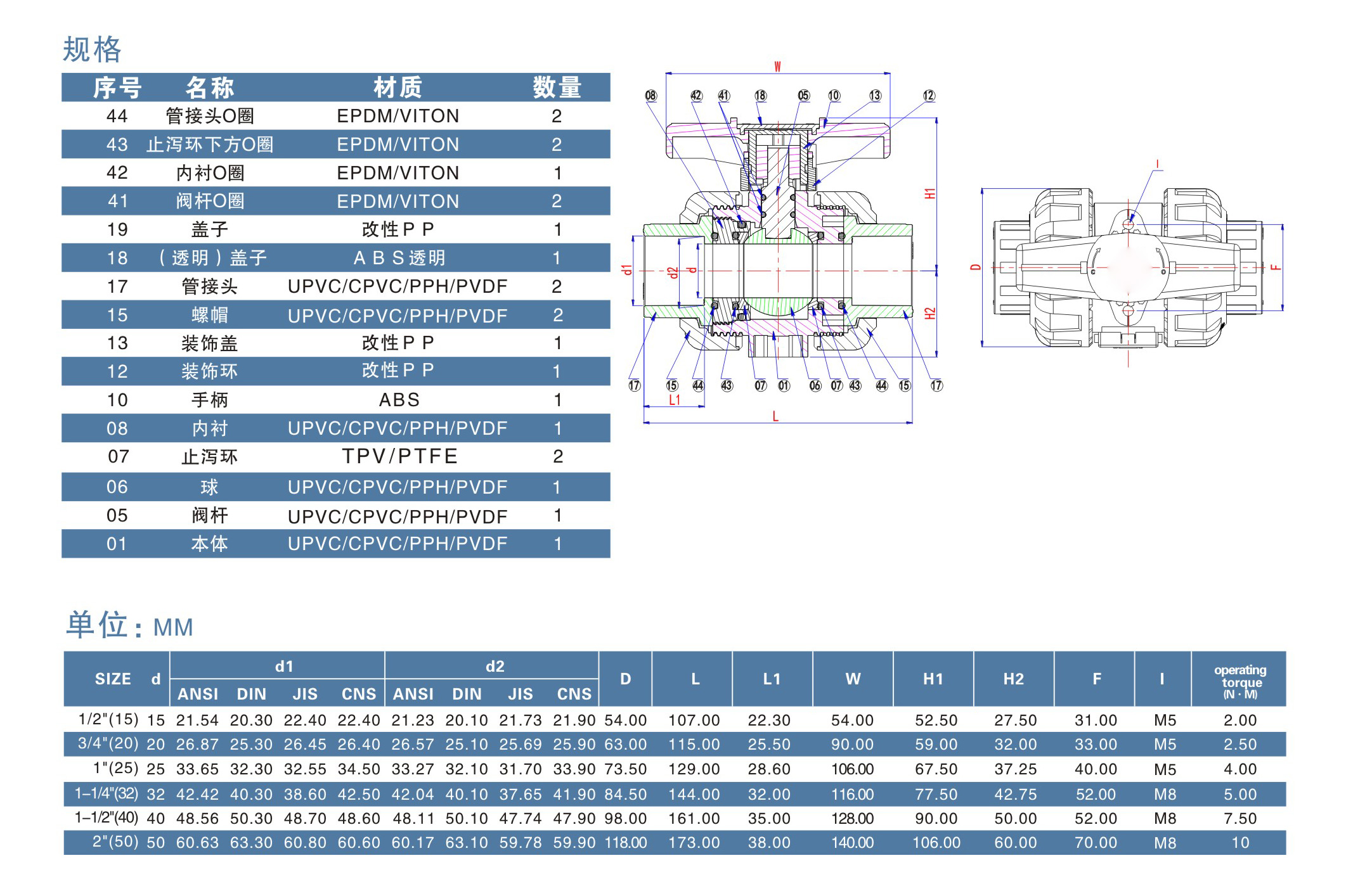
A100-T50-P2-C PP PVC plastic motorized valve drawing
A100-T50-P2-C PVC drawing
Technical Parameters:
| Valve size |
1/2"-2" |
| Maximum working pressure | 1.0 MPa |
| Circulation medium | Fluid, air |
| Rated voltage |
DC12v, DC24v,AC/DC9-24, AC110-230V |
| Wiring control methods |
CR2-01 CR2-02 CR3-03 CR3-05
CR4-01 CR5-01 CR5-02 CR7-04(Optional) |
| Working current | ≤800MA |
| Open/close time | ≤15S |
| Life time | 70000 times |
| Valve Body material | PPH,PVC |
| Actuator material | Engineering Plastics |
| Sealing material | EPDM & PTFE |
| Actuator rotation | 90° |
| Max. torque force | 10Nm |
| Cable Length | 0.5m,1.5m(Optional) |
| Environment temperature | -15℃~50℃ |
| Liquid temperature | 2℃~90℃ |
| Manual override | No |
| Indicator | Yes No |
| Protection class | IP67 |
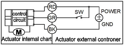
CR2 01 Wiring Diagram ( 2 wires control )
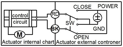
·RD connect with positive, the BK connect with negative, the valve closed, the actuator automatically power off after in place , the valve remains fully closed position .
·BK connect with positive, the RD connect with negative, the valve open, the actuator automatically power off after in place, the valve remains fully open position .
﹡Suitable Working Voltage: DC5V/DC12V/DC24V
﹡Exceeding the working voltage is forbidden
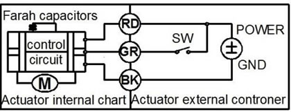
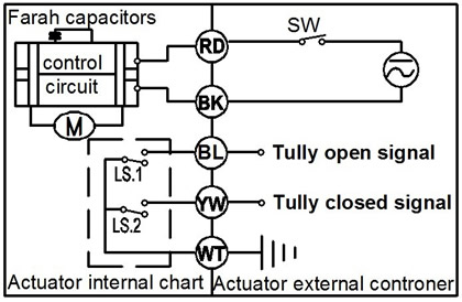
CR2 02 Wiring Diagram ( 2 wires control – Spring return in case of the power is failure)
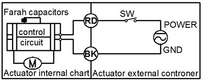
·When SW is closed , the valve open. the actuator automatically power off after in place
·When SW is open, the valve closed, the actuator automatically power off after in place
﹡Suitable Working Voltage: AC/DC9-24V,AC/DC110V-230V,AC/DC9-35V(with manual override).
﹡Exceeding the working voltage is forbidden
Please Note A100 CR2 02 must need charge time >1 minut for every time use
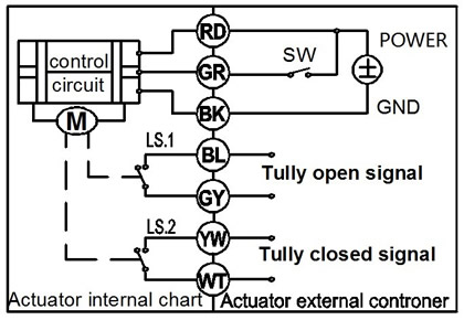
CR3 03 Wiring Diagram (3 wires control)
·RD& GR connect with positive, the BK connect with negative
·SW CLOSED, the valve OPEN, the actuator automatically power off after in place
·SW OPEN, the valve CLOSED, the actuator automatically power off after in place.
﹡Suitable Working Voltage: AC/DC9-24V/AC110-230V
﹡Exceeding the working voltage is forbidden
CR3 05 Wiring Diagram ( 3 wires control – Spring return in case of the power is failure)
·RD& GR connect with positive, the BK connect with negative
·SW CLOSED, the valve OPEN, the actuator automatically power off after in place
·SW OPEN, the valve CLOSED, the actuator automatically power off after in place.
When external power off, the valve closed, the actuator automatically power off after in place
﹡Suitable Working Voltage: AC/DC9-24V/AC110-230V
﹡Exceeding the working voltage is forbidden
CR4 01 Wiring Diagram (4 wires control )
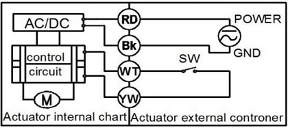
1、RD & BK are connected to the power, WT & YW are connected to the controlled wiring.
2、When the SW is closed , the valve open
3、When the SW is open , the valve closed Suitable Working Voltage::AC/DC110V-230V
Exceeding the working voltage is forbidden
The control wiring with power DC5V , when muitiple motorized valves are working in paralled , must put the same
color control wiring together, otherwise the valve could working normally .
CR5 01 Wiring diagram ( with feedback signal)
1. RD connect with positive, the BK connect with negative,the valve closed, the actuator automatically power off after in place .
2 BK connect with positive, the RD connect with negative,the valve open, the actuator automatically power off after in place .
3 GR & WT are connect when the valve open fully, YW & WT are connect when the valve closed fully
Suitable Working Voltage::DC5V/DC12V/DC24V
Exceeding the working voltage is forbidden
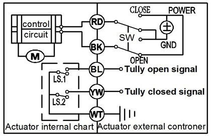
CR5 02 Wiring diagram ( with feedback signal)
·When SW is closed , the valve open. the actuator automatically power off after in place
·When SW is open, the valve closed, the actuator automatically power off after in place
﹡BL & WT are connect when the valve open fully, YW & WT are connect when the valve closed fully
﹡Suitable Working Voltage: AC/DC9-24V, AC/DC9-35V, AC/DC110V-230V
﹡Exceeding the working voltage is forbidden
CR7 04 Wiring Diagram ( 7 wires control with feedback signal )
·RD & BK are connected to the power, GR & GY are connected to the controlled wiring.
·When the SW is closed , the valve open
·When the SW is open , the valve closed
·BL & GY connect with the valve's fully open signal wiring
·YW & WT connect with the valve's fully closed signal wiring.
Suitable Working Voltage::AC/DC110V-230V
Exceeding the working voltage is forbidden
When you inquiry the valve, pls confirm the detail technical data :
1)valve size2)material, PVC? PP?
3)working voltage
4)wiring diagram
5)thread BSP or NPT or no thread?
6)quantity?
7)cable length, 0.5m is OK for you?