Tonheflow motorized valve manufacturer
Tonhe mainly produces motorized shut off ball valve from 1/4" to 2",
Some valves approved NSF61-G, CE, ROHS and other international certification.
News and Technical
A150 motorized valve with manual override motorized valve control circuit
Taizhou Tonhe Flow Control Co., Ltd
Email:tohe08@china-tonhe.com Skype:meizi2661
Mobile:+86-18957612187
URL:www.china-tonhe.com | www.tonheflow.com
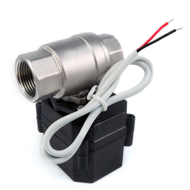
A150 Series
A150 torque 15NM,with manual override,
Actuator model: turn on off type,proportional type, timer control type (optional)
Wiring diagram Turn on/off type
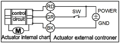
CR201(2 wires control)

·RD connect with positive, the BK connect with negative, the valve closed, the actuator automatically power off after in place , the valve remains fully closed position .
·BK connect with positive, the RD connect with negative, the valve open, the actuator automatically power off after in place, the valve remains fully open position .
﹡Suitable Working Voltage: DC12V, DC24V
﹡Exceeding the working voltage is forbidden
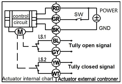
CR501(5 wires control,with feedback wire)
1. RD connect with positive, the BK connect with negative,the valve closed, the actuator automatically power off after in place .
2 BK connect with positive, the RD connect with negative,the valve open, the actuator automatically power off after in place .
4. GR & WT are connect when the valve open fully, YW & WT are connect when the valve closed fully
Suitable Working Voltage:DC12V, DC24V
Exceeding the working voltage is forbidden
Feedback wire capacity:
1. Voltage: DC0-35v; 2. Maximum current: 0.4A
CR202 (2 wires control--- Reset function, Normally closed or normally open)
·When SW is closed , the valve open. the actuator automatically power off after in place
·When SW is open, the valve closed, the actuator automatically power off after in place
﹡Suitable Working Voltage: AC24V,DC12-24V
﹡Exceeding the working voltage is forbidden
Please Note A150 CR202 must need charge time >1 minute for every time use
CR502 ( 5 wires control,Reset function,With feedback signal)
·When SW is closed , the valve open. the actuator automatically power off after in place
·When SW is open, the valve closed, the actuator automatically power off after in place
﹡GR & WT are connect when the valve open fully, YW & WT are connect when the valve closed fully
﹡Suitable Working Voltage: AC24V,DC12-24V
﹡Exceeding the working voltage is forbidden
Feedback wire capacity:
1. Voltage: DC0-35v; 2. Maximum current: 0.4A
Please Note A150 CR202 must need charge time >1 minute for every time use
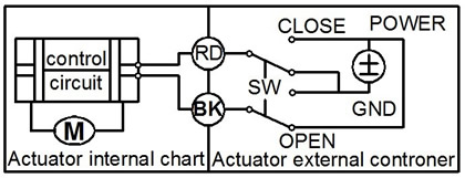
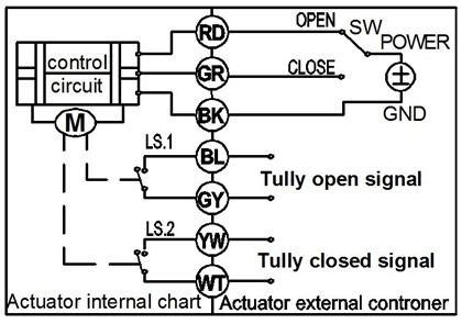
CR301(3 wires control)
·RD & GR connect with positive, BK connect with negative
·When OPEN( RD) & SW connected , the valve open, the actuator automatically power off after in place , valve remains fully open position
·When CLOSE(GR) & SW connected, the valve closed, the actuator automatically power off after in place, valve remains fully closed position.
﹡Suitable Working Voltage: DC12V, DC24V,AC24v,DC12v-24v
﹡Exceeding the working voltage is forbidden
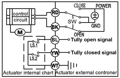
CR702(7 wires control)
1.RD & GR connect with positive, the BK connect with negative
2. When RD & SW connected, the valve open, the actuator automatically power off after the valve fully open.
3. When GR & SW connected, the valve closed, the actuator automatically power off after the valve fully closed,.
4. BL & GY connect with the valve’s fully open signal wiring
5. YW & WT connect with the valve’s fully closed signal wiring
﹡Suitable Working Voltage: DC12V, DC24V,AC24v,DC12v-24v
﹡Exceeding the working voltage is forbidden
l Feedback wire capacity:
1. Voltage: DC0-35v; 2. Maximum current: 0.4A
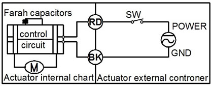
CR3 03 Wiring Diagram (3 wires control )
·RD connect with positive, GR connect with SW & positive
·BK connect with negative
·When the SW of GR closed, the valve OPEN, the actuator automatically power off after in place , remains fully closed position
·When the SW of GR open, the valve CLOSED, the actuator automatically power off after in place , remains fully open position.
﹡Suitable Working Voltage: DC12V, DC24V,AC24v,DC12-24v
﹡Exceeding the working voltage is forbidden
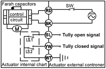
CR7 03 Wiring Diagram ( 7 wires control with feedback signal )
·RD& GR connect with positive, the BK connect with negative。
·SW CLOSED, the valve OPEN, the actuator automatically power off after in place
·SW OPEN, the valve CLOSED, the actuator automatically power off after in place.
·BL & GY connect with the valve’s fully open signal wiring
·YW & WT connect with the valve’s fully closed signal wiring.
﹡Suitable Working Voltage: DC12V, DC24V,AC24V,DC12-24V
﹡Exceeding the working voltage is forbidden
Feedback wire capacity:
1. maximum voltage DC36V, AC220V; 2. maximum current 0.4 A.
Taizhou Tonhe Flow Control Co.,Ltd
Add: Xincheng Road 1012, Huangyan, Taizhou, Zhejiang, China
Tel: 86-0576-81100233/84297288
Fax: 86-0576-81100232
Email:tonhe08@china-tonhe.com
Service On Line
URL: www.motorized-valve.com
www.tonheflow.com www.china-tonhe.com
