Tonheflow motorized valve manufacturer
Tonhe mainly produces motorized shut off ball valve from 1/4" to 2",
Some valves approved NSF61-G, CE, ROHS and other international certification.
News and Technical
Tonhe A20 2 port motorised valve wiring
Wiring diagram
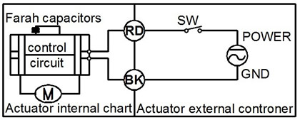
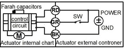
CR2 01 Wiring Diagram ( 2 wires control )
·RD connect with positive, the BK connect with negative, the valve closed, the actuator automatically power off after in place , the valve remains fully closed position .
·BK connect with positive, the RD connect with negative, the valve open, the actuator automatically power off after in place, the valve remains fully open position .
﹡Suitable Working Voltage: DC5V, DC12V, DC24V
﹡Exceeding the working voltage is forbidden
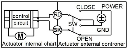
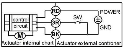
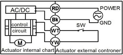
CR2 02 Wiring Diagram ( 2 wires control – Power reset function)
·When SW is CLOSED, the valve OPEN, the actuator automatically power off after in place.
·When SW is OPEN, the valve CLOSED, the actuator automatically power off after in place.
﹡Suitable Working Voltage: AC/DC9-35V,AC/DC110V-230V
﹡Exceeding the working voltage is forbidden
Please Note A20 CR2 02 must need charge time >10 seconds for every time use
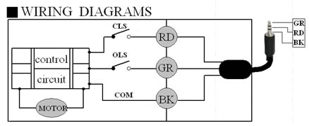
CR3 01 Wiring Diagram (3 wires control )
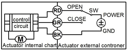
·RD & GR connect with positive, BK connect with negative
·When OPEN( RD) & SW connected , the valve open, the actuator automatically power off after in place , valve remains fully open position
·When CLOSE(GR) & SW connected, the valve closed, the actuator automatically power off after in place, valve remains fully closed position.
﹡Suitable Working Voltage: DC5V, DC12V, DC24V
﹡Exceeding the working voltage is forbidden
CR3 02 Wiring Diagram (3 wires control )
·RD connect with positive, the BK & GR connect with negative
·SW CLOSED, the valve OPEN, the actuator automatically power off after in place.
·SW OPEN, the valve CLOSED, the actuator automatically power off after in place.
﹡Suitable Working Voltage: DC7-35V
﹡Exceeding the working voltage is forbidden
CR3 03 Wiring Diagram (3 wires control)
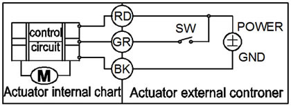
·RD& GR connect with positive, the BK connect with negative。
·SW CLOSED, the valve OPEN, the actuator automatically power off after in place
·SW OPEN, the valve CLOSED, the actuator automatically power off after in place.
﹡Suitable Working Voltage: AC/DC9-35V, AC110-230V
﹡Exceeding the working voltage is forbidden
CR3 04 Wiring Diagram ( 3 wires control )
·RD & GR connected with positive, and the BK connected with negative
·When RD & SW connected, the valve closed, the actuator automatically power off after in place , remains fully closed position
·When GR & SW connected, the valve open, the actuator automatically power off after in place , remains fully open position.
﹡Suitable Working Voltage: DC5V, DC12V, DC24V
﹡Exceeding the working voltage is forbidden
CR3 05 Wiring Diagram ( 3 wires control – Power reset funtion)
·RD& GR connect with positive, the BK connect with negative。
·SW CLOSED, the valve OPEN, the actuator automatically power off after in place
·SW OPEN, the valve CLOSED, the actuator automatically power off after in place.
﹡Suitable Working Voltage: AC110-230V
﹡Exceeding the working voltage is forbidden
CR3 06 Wiring Diagram ( 3 wires control – Power reset funtion)
·RD& GR connect with positive, the BK connect with negative
·SW CLOSED, the valve close, the actuator automatically power off after in place
·SW OPEN, the valve open, the actuator automatically power off after in place.
﹡Suitable Working Voltage: AC/DC9-24V,AC/DC110V-230V
﹡Exceeding the working voltage is forbidden
CR4 01 Wiring Diagram (4 wires control )
1、RD & BK are connected to the power, GY& GR are connected to the controlled wiring.
2、When the SW is closed , the valve open
3、When the SW is open , the valve closed
*Suitable Working Voltage:AC110V-230V
*Exceeding the working voltage is forbidden
The control wiring with power DC5V/DC24V, when muitiple motorized valves are working in paralled, must put the same color control wiring together, otherwise the valve could working
CR5 01 Wiring diagram ( with feedback signal)
1.RD connect with positive, the BK connect with negative,the valve closed, the actuator automatically power off after in place .
2.BK connect with positive, the RD connect with negative,the valve open, the actuator automatically power off after in place .
3.GR & WT are connect when the valve open fully, YW & WT are connect when the valve closed fully
﹡Suitable Working Voltage::DC5V, DC12V, DC24V
﹡Exceeding the working voltage is forbidden!
CR5 02 Wiring diagram ( with feedback signal and Power reset funtion)
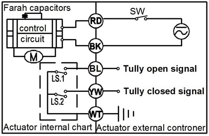
·When SW is closed , the valve open. the actuator automatically power off after in place
·When SW is open, the valve closed, the actuator automatically power off after in place
﹡GR & WT are connect when the valve open fully, YW & WT are connect when the valve closed fully
﹡Suitable Working Voltage: AC/DC9-35V,AC/DC110V-230V
﹡Exceeding the working voltage is forbidden
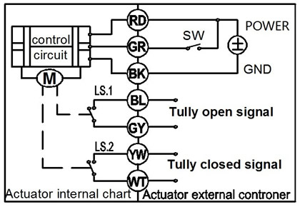
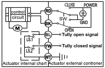
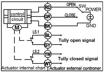
CR7 01 Wiring Diagram ( 7 wires control with feedback signal )
---RD connect with positive
---GR connect with SW and negative wiring
--- BK connect with negative wiring
---SW open. the valve open, and keeping fully open.
---SW closed. the valve closed, and keeping fully closed.
----BL & GY connect with the valve’s fully open signal wiring
--- YW & WT connect with the valve’s fully closed signal wiring.
﹡Suitable Working Voltage: DC7-35V (wide input range voltage)
﹡Exceeding the working voltage is forbidden
※ Feedback with load ability:
① The Max. off voltage: DC36V AC220V ② The Max. off current: ≦0.4A
CR7 02 Wiring Diagram ( 7 wires control with feedback signal )
1.RD & GR connect with positive, the BK connect with negative
2. When RD & SW connected, the valve open, the actuator automatically power off after the valve fully open.
3. When GR & SW connected, the valve closed, the actuator automatically power off after the valve fully closed,.
4. BL & GY connect with the valve’s fully open signal wiring
5. YW & WT connect with the valve’s fully closed signal wiring
﹡Suitable Working Voltage: DC5V, DC12V, DC24
﹡Exceeding the working voltage is forbidden
※ Feedback with load ability:
① The Max. off voltage: DC36V AC220V ② The Max. off current: ≦0.4A
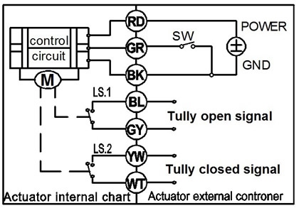
CR7 03 Wiring Diagram ( 7 wires control with feedback signal )

·RD& GR connect with positive, the BK connect with negative。
·SW CLOSED, the valve OPEN, the actuator automatically power off after in place
·SW OPEN, the valve CLOSED, the actuator automatically power off after in place.
·BL & GY connect with the valve’s fully open signal wiring
·YW & WT connect with the valve’s fully closed signal wiring.
﹡Suitable Working Voltage: AC/DC9-35V
﹡Exceeding the working voltage is forbidden
CR7 04 Wiring Diagram ( 7 wires control with feedback signal )
·RD & BK are connected to the power, GR & BL are connected to the controlled wiring.
·When the SW is closed , the valve open
·When the SW is open , the valve closed
·GR & WT connect with the valve’s fully open signal wiring
·YW & WT connect with the valve’s fully closed signal wiring.
Suitable Working Voltage::AC/DC110V-230V
﹡Exceeding the working voltage is forbidden