Tonheflow motorized valve manufacturer
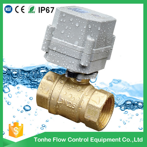
Tonhe mainly produces motorized shut off ball valve from 1/4" to 2",
Some valves approved NSF61-G, CE, ROHS and other international certification.
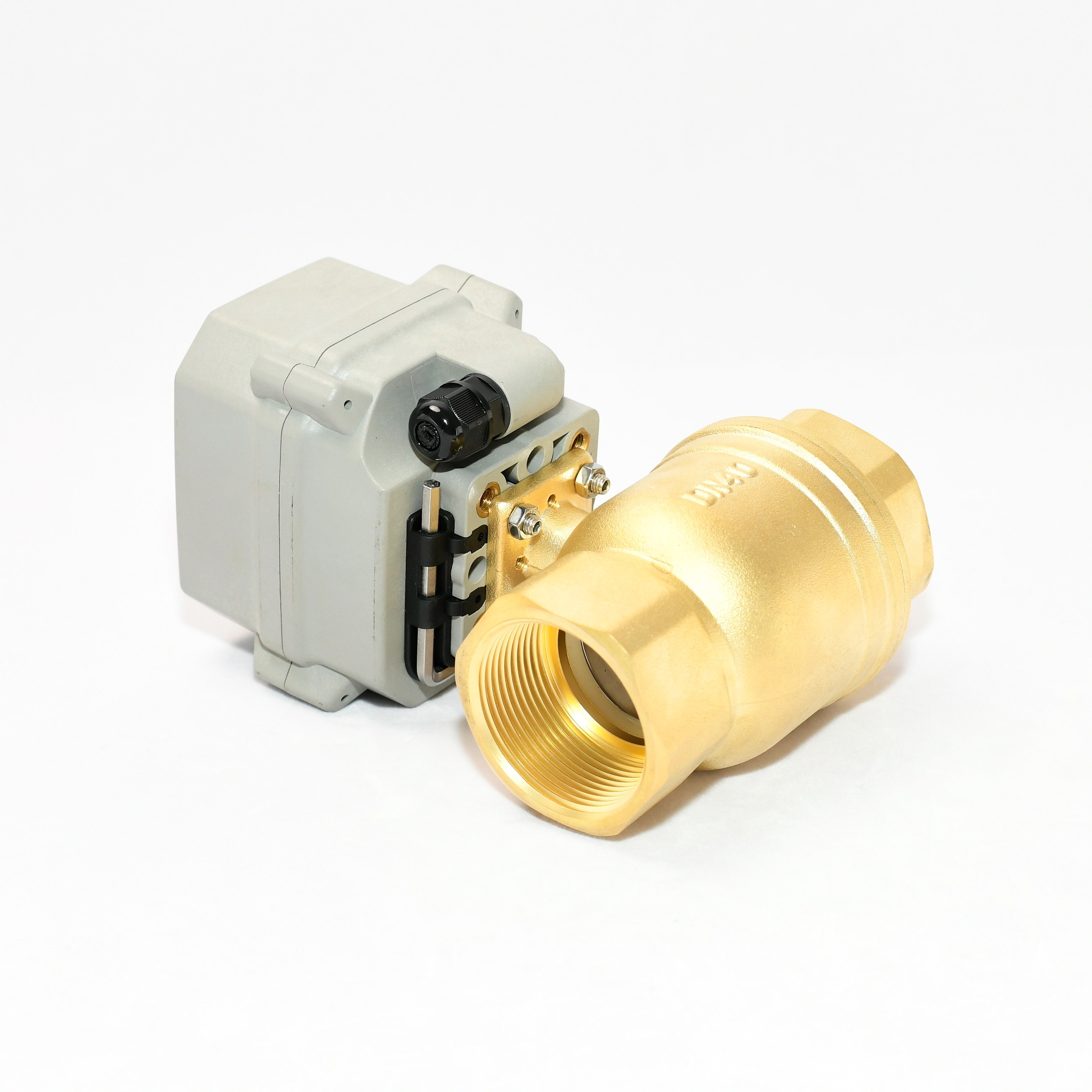
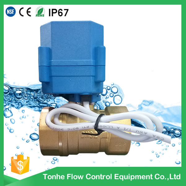
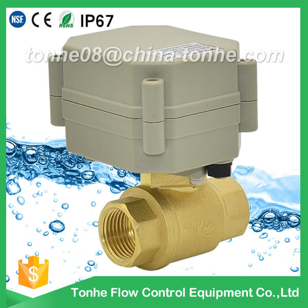
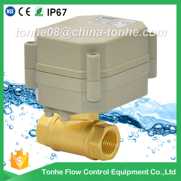
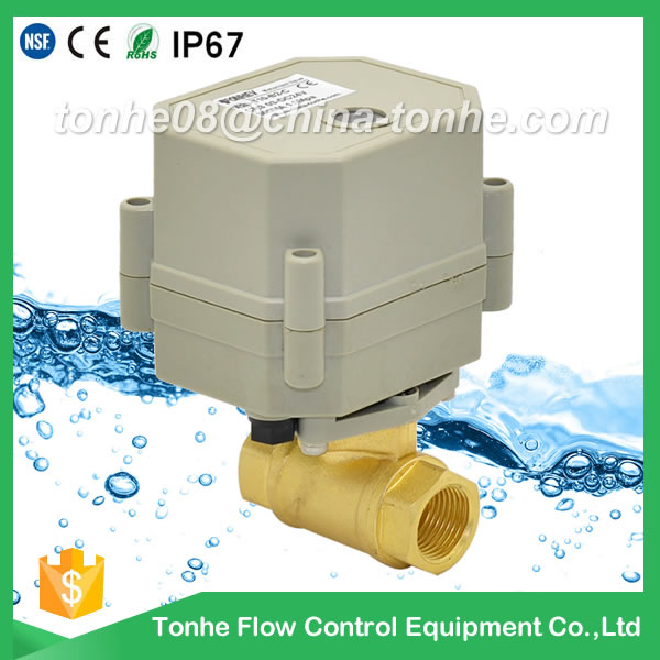
DN40 brass12v motorized ball valve electric brass water meter ball valve
Min.Order Quantity: 1 Piece/Pieces
Supply Ability: 5000 Piece/Pieces per Month
Port: ningbo,Shanghai
Payment : T/T, Paypal

Service On Line
Supply Ability: 5000 Piece/Pieces per Month
Port: ningbo,Shanghai
Payment : T/T, Paypal
Service On Line
Tonhe is a china manufacturer, we focus on mini motorized valve(1/4" - 2"), which are CE, RoHS, IP67 approved, and SS valve NSF61 approved. Our company also SGS ISO9001 approved.
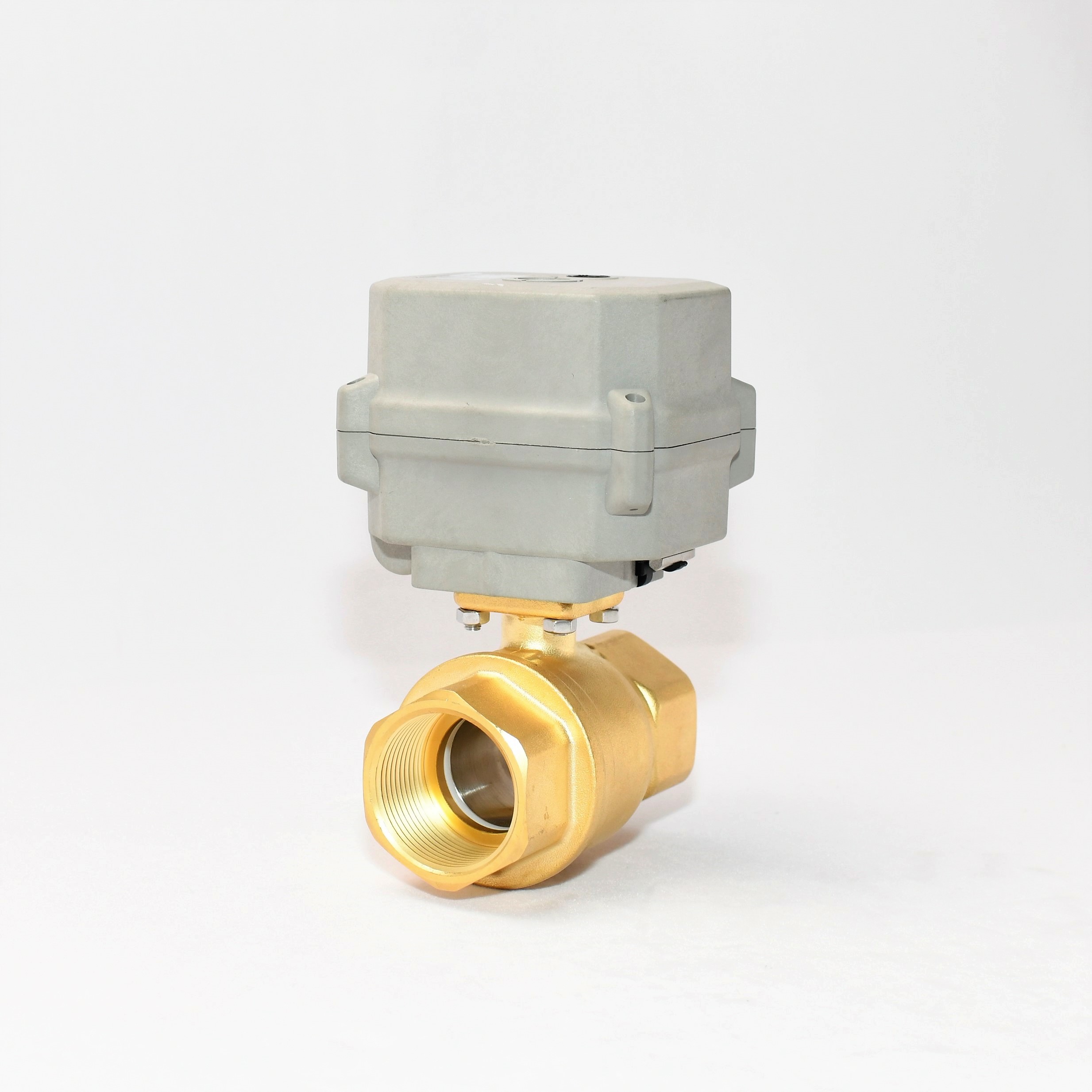
A150 motorized valve with manual override new feature
Technical Parameters:
| Valve size |
BSP/NPT 1 1/2" DN40 |
|
Connection standard |
ISO5211 F03、F05 |
|
Output axis specification |
Female octagonal 9*9 or 11*11 |
| Maximum working pressure | 1.0 MPa |
| Circulation medium | Fluid, air |
| Rated voltage |
DC12v, DC24v, DC9-24v,AC110-230V |
| Wiring control methods |
CR201,CR202, CR303,CR501, CR502,CR703, CR706 |
| Working current | ≤1.5A |
| Open/close time |
≤10S |
| Life time | 50000 times |
| Valve Body material |
Brass |
| Actuator material | Engineering Plastics |
| Sealing material | EPDM & PTFE |
| Actuator rotation | 90° |
| Max. torque force | 15Nm |
| Cable Length | 0.5m,1.5m(Optional) |
| Environment temperature | -15℃~50℃ |
| Liquid temperature | 2℃~120℃ |
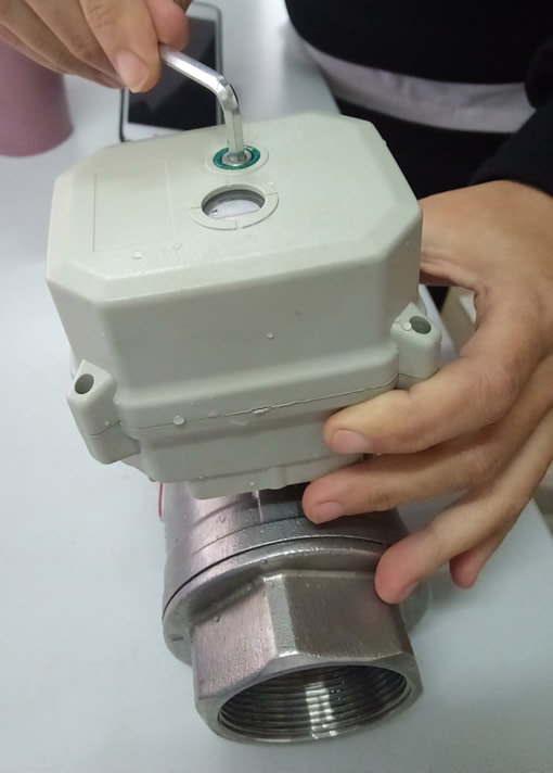
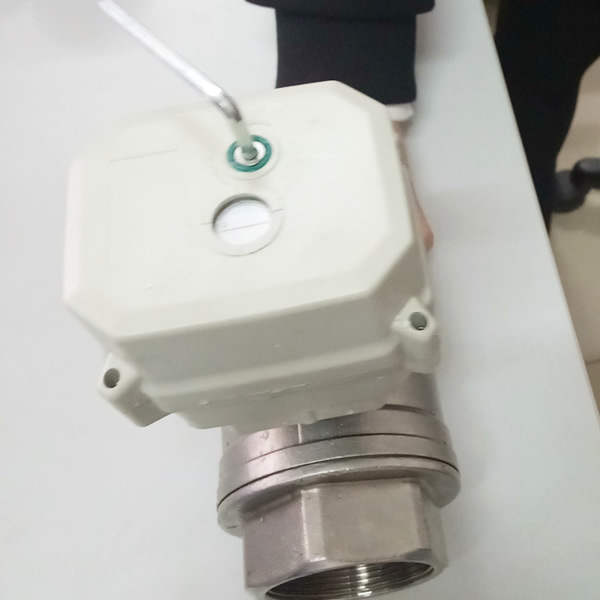
| Manual override | Yes |
| Indicator | Yes |
| Protection class | IP67 |
Motorized valve Data sheet + Assemble drawing
 A150 stainless stell motorized valve data sheet + 2D drawing
Wiring diagram
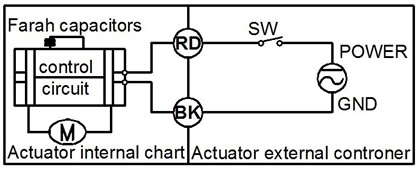
CR201 Wiring Diagram ( 2 wires control )
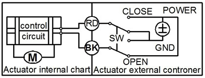
·RD connect with positive, the BK connect with negative, the valve closed, the actuator automatically power off after in place , the valve remains fully closed position .
·BK connect with positive, the RD connect with negative, the valve open, the actuator automatically power off after in place, the valve remains fully open position .
﹡Suitable Working Voltage: DC5V/DC12V/DC24V
﹡Exceeding the working voltage is forbidden
CR202 Wiring Diagram ( 2 wires control – Spring return in case of the power is failure)
·When SW is closed , the valve open. the actuator automatically power off after in place
·When SW is open, the valve closed, the actuator automatically power off after in place
﹡Suitable Working Voltage: AC/DC9-24V,AC/DC110V-230V,AC/DC9-35V(with manual override).
﹡Exceeding the working voltage is forbidden
CR301 Wiring Diagram (3 wires control)
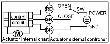
·RD & GR connect with positive, BK connect with negative
·When OPEN( RD) & SW connected , the valve open, the actuator automatically power off after in place , valve remains fully open position
·When CLOSE(GR) & SW connected, the valve closed, the actuator automatically power off after in place, valve remains fully closed position.
﹡Suitable Working Voltage: DC12V, DC24V,AC24v,DC12v-24v
﹡Exceeding the working voltage is forbidden
CR303 Wiring Diagram (3 wires control)
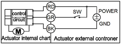
·RD& GR connect with positive, the BK connect with negative
·SW CLOSED, the valve OPEN, the actuator automatically power off after in place
·SW OPEN, the valve CLOSED, the actuator automatically power off after in place.
﹡Suitable Working Voltage: AC/DC9-35V/AC110-230V
﹡Exceeding the working voltage is forbidden
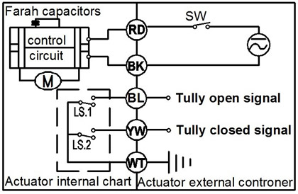
CR501 Wiring diagram ( with feedback signal)
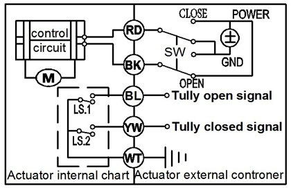
1. RD connect with positive, the BK connect with negative,the valve closed, the actuator automatically power off after in place .
2 BK connect with positive, the RD connect with negative,the valve open, the actuator automatically power off after in place .
3 GR & WT are connect when the valve open fully, YW & WT are connect when the valve closed fully
Suitable Working Voltage::DC5V/DC12V/DC24V
Exceeding the working voltage is forbidden
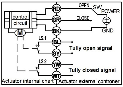
CR502 Wiring diagram ( with feedback signal)
·When SW is closed , the valve open. the actuator automatically power off after in place
·When SW is open, the valve closed, the actuator automatically power off after in place
﹡BL & WT are connect when the valve open fully, YW & WT are connect when the valve closed fully
﹡Suitable Working Voltage: AC/DC9-24V, AC/DC9-35V, AC/DC110V-230V
﹡Exceeding the working voltage is forbidden
CR702 Wiring Diagram ( 7 wires control with feedback signal )
1.RD & GR connect with positive, the BK connect with negative
2. When RD & SW connected, the valve open, the actuator automatically power off after the valve fully open.
3. When GR & SW connected, the valve closed, the actuator automatically power off after the valve fully closed,.
4. BL & GY connect with the valve's fully open signal wiring
5. YW & WT connect with the valve's fully closed signal wiring
﹡Suitable Working Voltage: DC12V, DC24V,AC24v,DC12v-24v
﹡Exceeding the working voltage is forbidden
Feedback wire capacity:
1. Voltage: DC0-35v; 2. Maximum current: 0.4A
When you inquiry the valve, pls confirm the detail technical data :
1)valve size2)material, brass or stainless steel or UPVC ?
3)working voltage
4)wiring diagram
5)thread BSP or NPT?
6)quantity?
7)cable length, 0.5m is OK for you?
8)Water pressure?
9)if you need manual override?
Relative Products:
-
- A20-T32-B2-C DN32 bras reduce port CR2 02 normally closed blue actuator motorized ball valve for air condition
-
- A20-T15-N2-A DN15 brass nickel plated CR2 02 normally closed motorized valve union connection
-
- A20-T15-B2-A CR2 01 DN15 brass motorized valve suit for water and gas
-
- A20-T25-B2-C DN25 1 inch DC12V brass NPT motorized ball valves-electric ball valve
-
- A150-T32-B2-B DN32 brass motorized valve 15NM with manual override
-
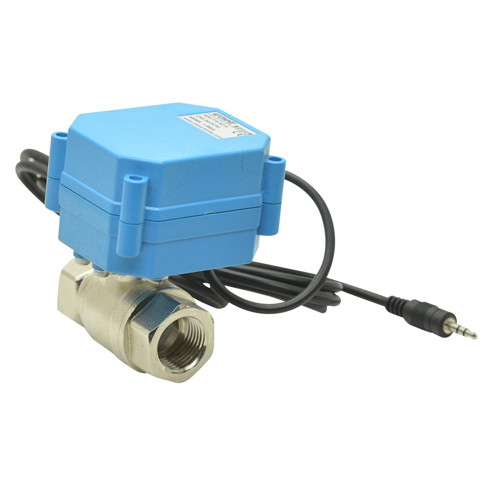
- A20-T15-N2-A electric actuated ball valve price with audio line
-
- A20-T10-B2-A DN10 brass motorized valve with custom terminal connector
-
- A20-T10-B2-C CR2 02 normally closed 230V motorized valve
