Tonheflow motorized valve manufacturer
Tonhe mainly produces motorized shut off ball valve from 1/4" to 2",
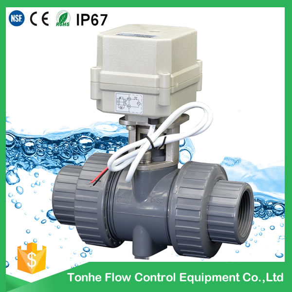
Some valves approved NSF61-G, CE, ROHS and other international certification.
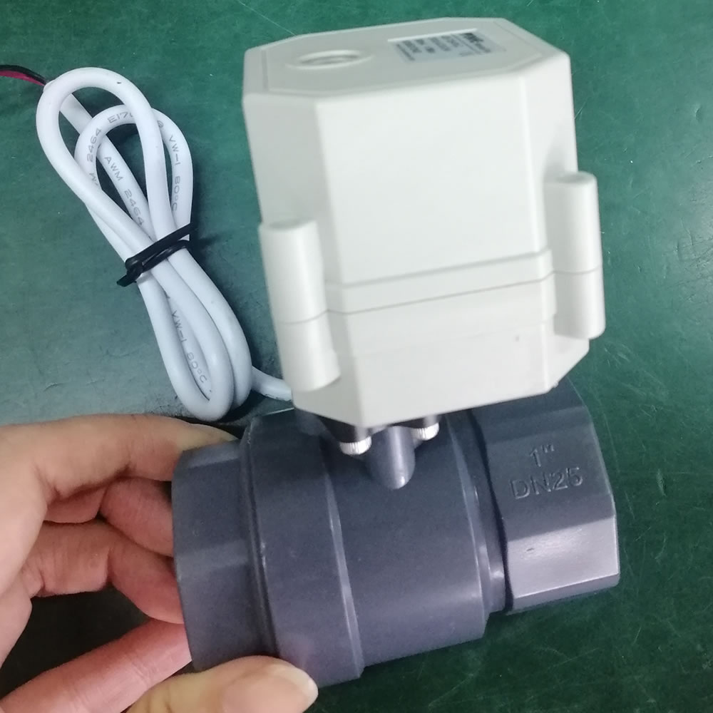
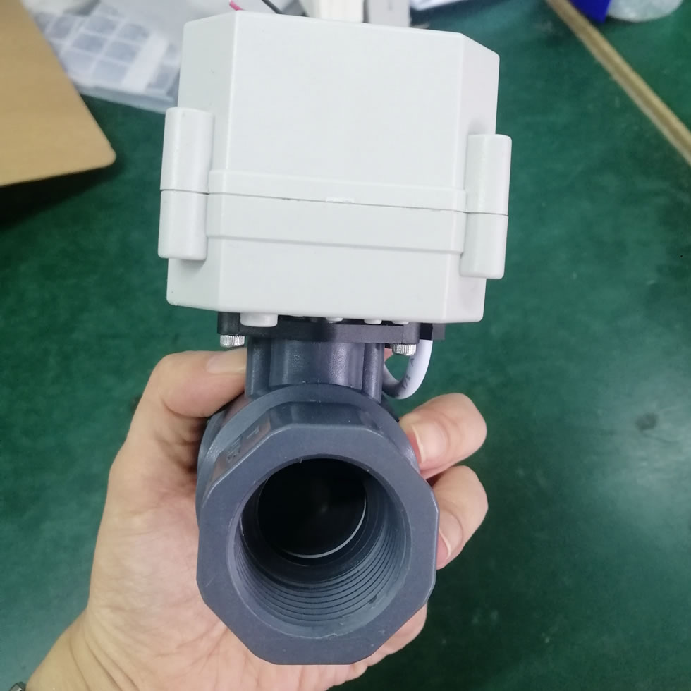
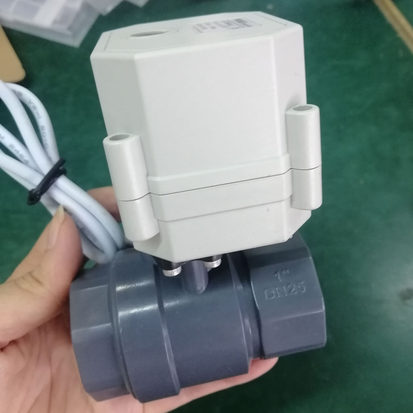
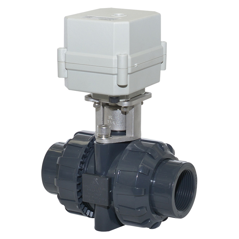
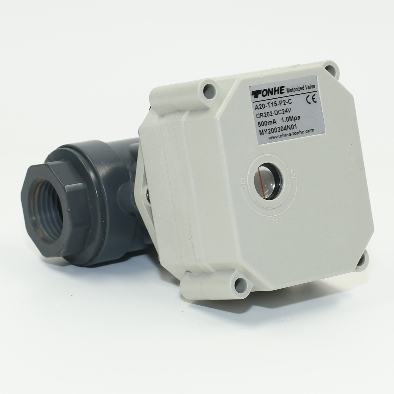
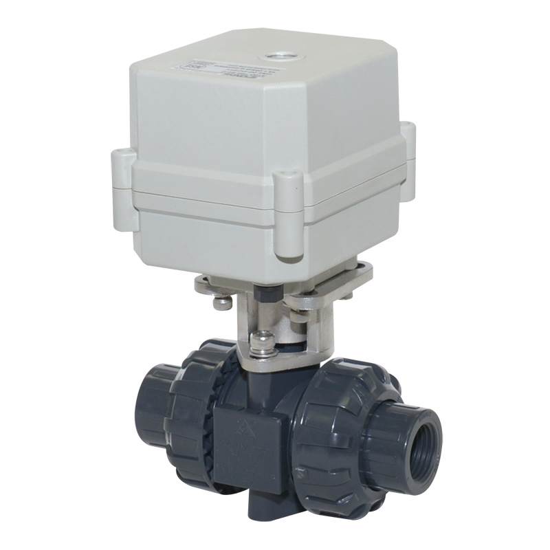
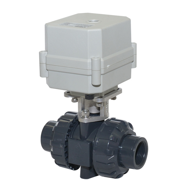
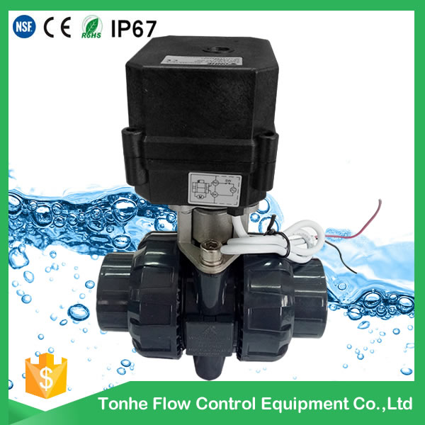
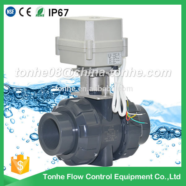
1 inch DN25 UPVC double union thread DC24V CR202 normally close pvc motorized ball valve
Min.Order Quantity: 1 Piece/Pieces
Supply Ability: 5000 Piece/Pieces per Month
Port: ningbo,Shanghai
Payment : T/T, Paypal

Service On Line
Supply Ability: 5000 Piece/Pieces per Month
Port: ningbo,Shanghai
Payment : T/T, Paypal
Service On Line
Tonhe is a china manufacturer, we focus on mini motorized valve(1/4" - 2"), which are CE, RoHS, IP67 approved, and SS valve NSF61 approved. Our company also SGS ISO9001 approved.
Our A20 4NM electric valve, product features: all stainless steel gear, 5v big torque motor, can be used for client demand big torque when 2NM is not enough for thir system
Our A20 4NM electric valve, product features: all stainless steel gear, 5v big torque motor, can be used for client demand big torque when 2NM is not enough for thir system
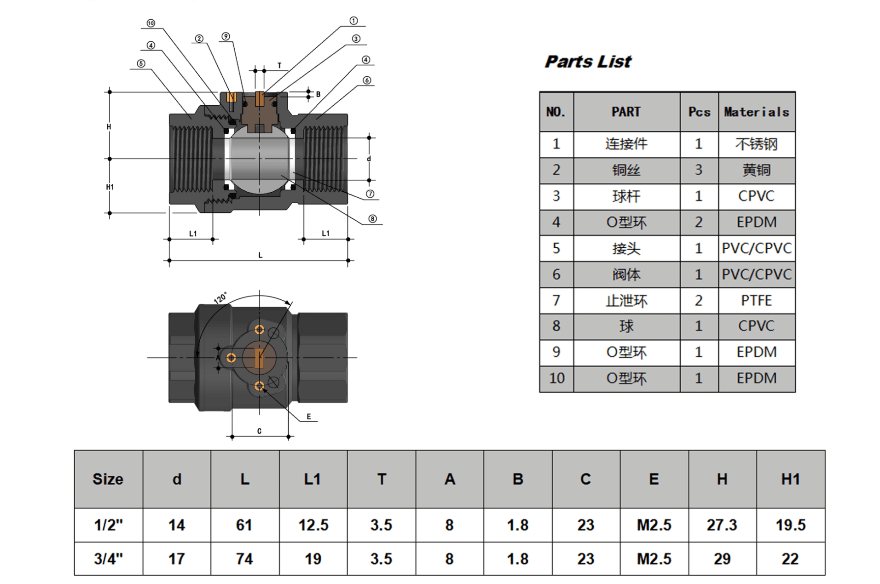
Technical Parameters:
| Valve size |
BSP NPT 1" DN25 |
| Maximum working pressure | 1.0 MPa |
| Circulation medium | Fluid, air |
| Rated voltage |
DC9-24V |
| Wiring control methods |
CR202 normally closed |
| Working current | ≤500MA |
| Open/close time |
≤5S |
| Life time | 70000 times |
| Valve Body material |
UPVC |
| Actuator material | Engineering Plastics |
| Sealing material | EPDM & PTFE |
| Actuator rotation | 90° |
| Max. torque force | 2 Nm/4Nm(Optional) |
| Cable Length | 0.5m,1.5m(Optional) |
| Environment temperature | -15℃~50℃ |
| Liquid temperature | 2℃~90℃ |
| Manual override | No |
| Indicator | Yes |
| Protection class | IP67 |
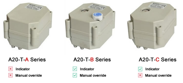
Pls confirm below different versions of actuators
Our actuators have three options,A type: without indicator and manual override,
C type:with indicator,
B type: with indicator and manual override
Assemble drawing
Wiring diagram
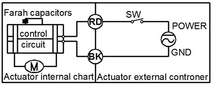
CR2 01 Wiring Diagram ( 2 wires control )
·RD connect with positive, the BK connect with negative, the valve closed, the actuator automatically power off after in place , the valve remains fully closed position .
·BK connect with positive, the RD connect with negative, the valve open, the actuator automatically power off after in place, the valve remains fully open position .
﹡Suitable Working Voltage: DC5V/DC12V/DC24V
﹡Exceeding the working voltage is forbidden
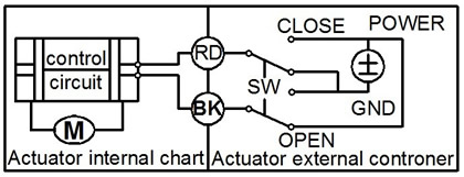
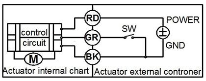
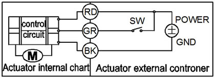
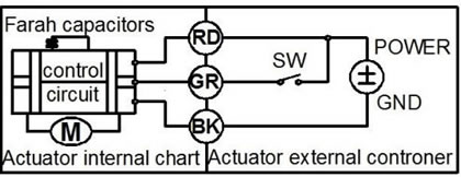
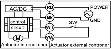
CR2 02 Wiring Diagram ( 2 wires control – Spring return in case of the power is failure)
·When SW is closed , the valve open. the actuator automatically power off after in place
·When SW is open, the valve closed, the actuator automatically power off after in place
﹡Suitable Working Voltage: AC/DC9-24V,AC/DC110V-230V,AC/DC9-35V(with manual override).
﹡Exceeding the working voltage is forbidden
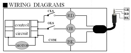
CR3 01 Wiring Diagram (3 wires control )
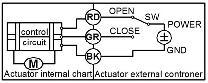
·RD & GR connect with positive, BK connect with negative
·When OPEN( RD) & SW connected , the valve open, the actuator automatically power off after in place , valve remains fully open position
·When CLOSE(GR) & SW connected, the valve closed, the actuator automatically power off after in place, valve remains fully closed position.
﹡Suitable Working Voltage: DC5V/DC12V/DC24V/AC/DC9-35V
﹡Exceeding the working voltage is forbidden
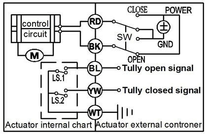
CR3 02 Wiring Diagram (3 wires control )
·RD connect with positive, the BK & GR connect with negative
·SW CLOSED, the valve OPEN, the actuator automatically power off after in place.
·SW OPEN, the valve CLOSED, the actuator automatically power off after in place.
﹡Suitable Working Voltage: DC9-35V
﹡Exceeding the working voltage is forbidden
CR3 03 Wiring Diagram (3 wires control)
·RD& GR connect with positive, the BK connect with negative
·SW CLOSED, the valve OPEN, the actuator automatically power off after in place
·SW OPEN, the valve CLOSED, the actuator automatically power off after in place.
﹡Suitable Working Voltage: AC/DC9-35V/AC110-230V
﹡Exceeding the working voltage is forbidden
CR3 04 Wiring Diagram ( 3 wires control )
·RD & GR connected with positive, and the BK connected with negative
·When RD & SW connected, the valve closed, the actuator automatically power off after in place , remains fully closed position
·When GR & SW connected, the valve open, the actuator automatically power off after in place , remains fully open position.
﹡Suitable Working Voltage: DC5V/DC12V/AC/DC9-35V
﹡Exceeding the working voltage is forbidden
CR3 05 Wiring Diagram ( 3 wires control – Spring return in case of the power is failure)
·RD& GR connect with positive, the BK connect with negative
·SW CLOSED, the valve OPEN, the actuator automatically power off after in place
·SW OPEN, the valve CLOSED, the actuator automatically power off after in place.
When external power off, the valve closed, the actuator automatically power off after in place
﹡Suitable Working Voltage: AC110-230V
﹡Exceeding the working voltage is forbidden
CR4 01 Wiring Diagram (4 wires control )
1、RD & BK are connected to the power, WT & YW are connected to the controlled wiring.
2、When the SW is closed , the valve open
3、When the SW is open , the valve closed Suitable Working Voltage::AC/DC110V-230V
Exceeding the working voltage is forbidden
The control wiring with power DC5V , when muitiple motorized valves are working in paralled , must put the same
color control wiring together, otherwise the valve could working normally .
CR5 01 Wiring diagram ( with feedback signal)
1. RD connect with positive, the BK connect with negative,the valve closed, the actuator automatically power off after in place .
2 BK connect with positive, the RD connect with negative,the valve open, the actuator automatically power off after in place .
3 GR & WT are connect when the valve open fully, YW & WT are connect when the valve closed fully
Suitable Working Voltage::DC5V/DC12V/DC24V
Exceeding the working voltage is forbidden
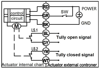
CR5 02 Wiring diagram ( with feedback signal)
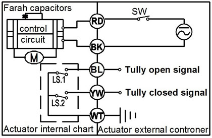
·When SW is closed , the valve open. the actuator automatically power off after in place
·When SW is open, the valve closed, the actuator automatically power off after in place
﹡BL & WT are connect when the valve open fully, YW & WT are connect when the valve closed fully
﹡Suitable Working Voltage: AC/DC9-24V, AC/DC9-35V, AC/DC110V-230V
﹡Exceeding the working voltage is forbidden
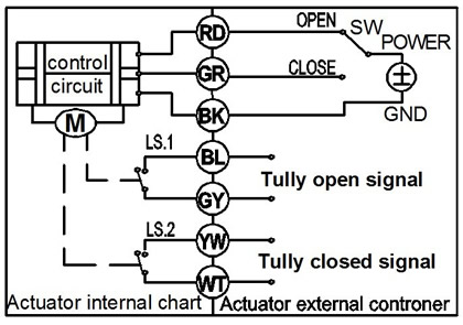
CR7 01 Wiring Diagram ( 7 wires control with feedback signal )
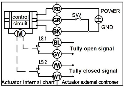
---RD connect with positive
---GR connect with SW and negative wiring
--- BK connect with negative wiring
---SW open. the valve open, and keeping fully open.
---SW closed. the valve closed, and keeping fully closed.
----BL & GY connect with the valve's fully open signal wiring
--- YW & WT connect with the valve's fully closed signal wiring.
﹡Suitable Working Voltage: DC5V,DC12V,DC24V,AC/DC9-35V(wide input range voltage,)
﹡Exceeding the working voltage is forbidden
※ Feedback with load ability:
① The Max. off voltage: DC36V AC220V
② The Max. off current: ≦0.4A
CR7 02 Wiring Diagram ( 7 wires control with feedback signal )
1.RD & GR connect with positive, the BK connect with negative
2. When RD & SW connected, the valve open, the actuator automatically power off after the valve fully open.
3. When GR & SW connected, the valve closed, the actuator automatically power off after the valve fully closed.
4. BL & GY connect with the valve's fully open signal wiring
5. YW & WT connect with the valve's fully closed signal wiring
﹡Suitable Working Voltage: DC5V/DC12V/DC24V
﹡Exceeding the working voltage is forbidden
※ Feedback with load ability:
① The Max. off voltage: DC36V AC220V
② The Max. off current: ≦0.4A
CR7 04 Wiring Diagram ( 7 wires control with feedback signal )
·RD & BK are connected to the power, GR & GY are connected to the controlled wiring.
·When the SW is closed , the valve open
·When the SW is open , the valve closed
·BL & GY connect with the valve's fully open signal wiring
·YW & WT connect with the valve's fully closed signal wiring.
Suitable Working Voltage::AC/DC110V-230V
Exceeding the working voltage is forbidden
Valve Actuator gear
our A20 actuator gear is brass(biggest gear) + stainless steel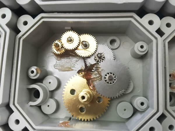
Our electronic components are basically imported, all choose the better quality of the accessories, such as switches, we use better quality Taiwan switch.
When you inquiry the valve, pls confirm the detail technical data :
1)valve size2)material, brass or stainless steel or PVC?
3)working voltage
4)wiring diagram
5)thread BSP or NPT?
6)quantity?
7)cable length, 0.5m or 1.5m?
Relative Products:
-
- A100-T32-P2-C DN32 PVC NSF approved electric Motorized ball valve
-
- DN15 1 2 UPVC motorized motorised ball valve 12v pvc
-
- A100-T15-P2-C DN15 PVC UPVC plastic motorized valve
-
- A100-T20-P2-C DN20 PVC UPVC plastic motorized true union valve
-
.jpg)
- 2 way DN32 ANSI standard CR501 24vDC UPVC motorized valve for pvc pipe
-
- A100-T20-P2-C DN20 PVC UPVC plastic motorized valve normally closed
-
- A20-T15-P2-C 0.5 inch GIN ANSI standard PVC motorized valve black actuator normally closed
-
- A100-T50-P2-C DN 50 2 inch AC 110-230V Female Solvent socket type CPVC PVC motorized valve
